Draw the flat. Add the flanges.
Watch it fold. Print the bend sheet.
Sheet metal for the press brake, in your browser. Build a tray, box, channel or bracket from a few numbers, or grow flanges off an outline you have already drawn. The flat is right by construction, the folded part is on screen while you work, and the shop gets a traveller it can work from.
The whole job — a 120 mm fan cutout in a steel enclosure, two minutes
A box from six numbers, the fan cutout drawn as an ordinary circle, the check that catches a hole too near a bend, then the traveller for the brake and the DXF for the laser.
Angle bracket — 140 × 160 × 90 in 2 mm, three bends
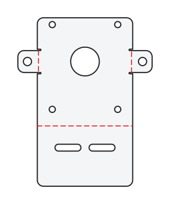
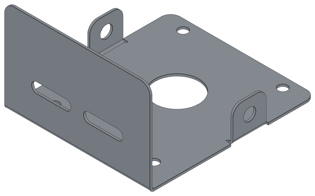
Draw the flat, mark where it folds, and the part is built from it. Move a hole and it moves on the folded part too — there is no second model to keep in step.
Box — 300 × 200 × 50 with a 15 mm return lip, eight bends
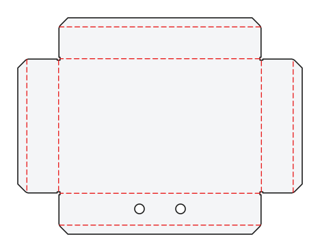
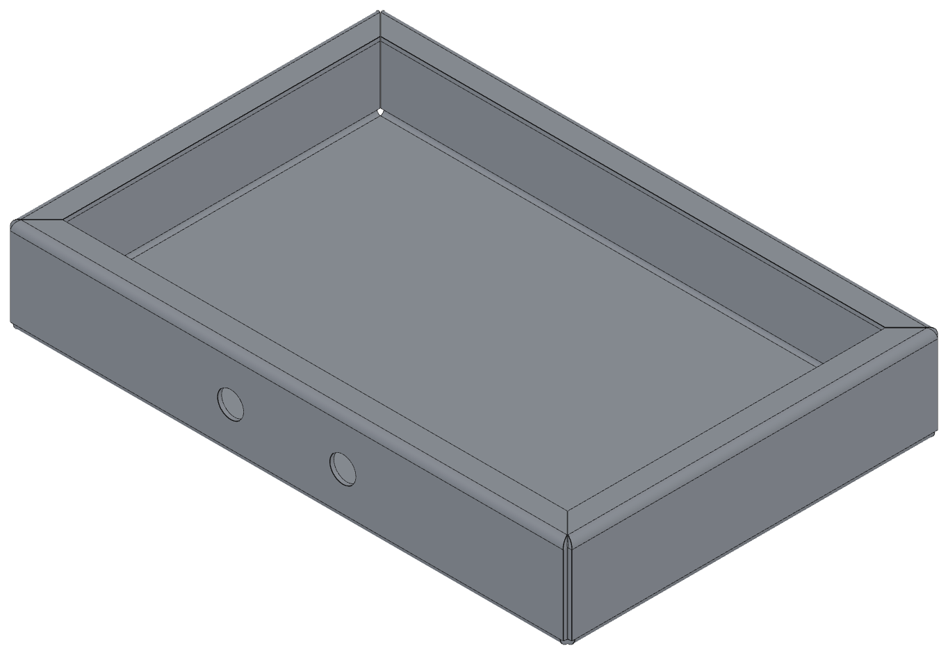
Corners are cut so the walls stand the right gap apart once folded, and each lip is mitred where it meets its neighbour. Both are worked out from the material and the radius, not guessed.
Three steps to a part the shop can make
From a few numbers to a printable traveller, without leaving the drawing.
A few numbers to a part
Pick a tray, box, channel, hat, bracket or enclosure and type the sizes. Choose the material and thickness from the table. The whole part is built, every corner is cut so it will fold, and it folds on screen as it appears.
Your holes and cutouts, drawn normally
Draw circles, slots and cutouts on a wall the way you draw anything else — they belong to that wall and fold with it. Or start from an outline of your own and add flanges, hems and jogs to any edge. Select every edge first and answer once: a tray with a return on all four walls is eleven answers, not sixty.
The checks, then the traveller
Corners that cannot be folded, holes too near a bend, flanges too short for the brake — each is marked on the drawing with the repair offered in place. When the panel says Ready to make, print the traveller: the flat at a stated scale, the bend table, the material block and an isometric of the folded part.
Who this is for
Being straight about the edges of it is what makes the rest believable.
A good fit
- Shops that design their own parts — enclosures, trays, brackets, guards, chassis
- Shops that fold from a customer's flat and need the bend numbers checked before it goes on the brake
- Anyone quoting laser or punch work who needs a clean cut file out of a folded design
- Drafters who want the flat and the folded part to stay in step without redrawing either
- Small teams who would rather not run a second CAD package just for sheet metal
Not a fit
- Cones, transitions and elbows — anything rolled or curved
- Ducting and round work
- Deep-drawn or stamped parts
- Weldments and frames as an assembly
- Full 3D parametric modelling — the flat is the truth here, and the 3D view is a picture of it
Say it plainly: this is press-brake work. Straight bends, flanges, hems and jogs. Nothing rolled or curved — no cones, no transitions, no elbows.
What you need to run it
Sheet Metal is an add-on that sits on top of the Standard plan. All of it — building, folding, checking, the traveller and the cut file — is behind the trial.
Try Sheet Metal free for 14 days
No card. When it ends your drawings stay exactly as they are; editing them as parts stops until you add Sheet Metal to your plan.
| What you get | Standard | Standard + Sheet Metal |
|---|---|---|
| Open, draw and edit DWG and DXF | Yes | Yes |
| Save DWG and DXF, export PDF | Yes | Yes |
| Build a tray, box, channel, hat, bracket or enclosure from its sizes | — | Yes |
| Flanges, hems and jogs on your own outline | — | Yes |
| Corner relief cut automatically so the part folds | — | Yes |
| The folded part in 3D — orbit, section, measure | — | Yes |
| Checks: corners that cannot fold, holes near a bend, flanges too short | — | Yes |
| Material and bend table, K-factor, allowance or deduction | — | Yes |
| Re-cut the part for a new thickness or K-factor | — | Yes |
| The printable shop traveller | — | Yes |
| Cut file for the laser or an online cutting service | — | Yes |
Prices exclude tax. Local display pricing is available in AUD, USD, EUR, CAD and GBP.
Questions a fabricator asks first
Does it read my existing DXF flat patterns?
Yes. Open the DXF and draw the bend lines across it, or bring in a file that already has them. Bend lines are plain lines on a layer named BEND, and the FOLD_UP / FOLD_DOWN convention is read too. The layer names are configurable, so you map them once to whatever your shop already uses.
Where do the fold lines go?
On their own layer, so they never reach the cutter. A part built here puts them there automatically; a part you bring in keeps whatever layer it arrived on, and you map that layer on import. The cut file export leaves the whole sheet metal model out, so the laser gets only the part.
K-factor, bend allowance or bend deduction — which does it want?
Whichever you already use. Give it any one of the three and the other two are worked out from it, so you can type the number your press brake operator quotes. There is a starter table of 45 rows covering common materials and thicknesses, in millimetres and in inches, and every value in it is editable. A metric drawing is only offered the metric rows.
Is this 3D CAD?
No. The flat is the truth and the 3D view is a picture of it. You draw and edit in 2D as you always have; the folded part on screen is generated from the flat so you can see what you are about to make, orbit it, section it and measure it. Click a face in the flat and it lights up in 3D, and the other way round.
What happens if I change the thickness or the material?
The part is re-cut from its recovered blank for the new thickness or K-factor, and holes move with the wall they belong to. You can also change one bend's angle, direction or radius on its own without touching the rest.
Does it do cones, transitions or elbows?
No, and it is not going to pretend otherwise. Nothing rolled or curved. This is press-brake work: straight bends, flanges, hems and jogs. If your work is ducting, cones or lobster-back elbows, this is not the tool for it.
Will the file open in the CAD software my customers use?
Yes. Parts are ordinary DWG and DXF. A part made here opens correctly in other CAD software and comes back unchanged — that round trip is tested, not assumed.
How do I know the flat is right?
Because it is built rather than measured: the flat and the folded part come from the same model, so they cannot disagree. Against 56 real production parts, 55 rebuild and fold to a median of 0.001 mm of the part's own 3D model.
What does it cost, and what happens when the trial ends?
Sheet Metal is an add-on on top of Standard — the price in your currency is above. Try it free for 14 days with no card. When the trial ends your drawings are unchanged and still open, and every line on them stays where it is; what stops is editing them as parts.
Build a part and watch it fold
Open it in your browser, pick a shape, type six numbers. You will have a folded part and a bend table inside a minute.
Send a flat and we will fold it, check it and send the job sheet back. Tell us the material and thickness in the message and we will ask for the DXF by reply.